Angle Constraint
Fixed angle between two frame Z axes
Description
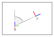
This block applies a fixed angle between the Z axes of the base and follower port frames. The frames lose one rotational degree of freedom if the constraint angle is greater than 0° and smaller than 180°. They lose two rotational degrees of freedom if the constraint angle is exactly 0° or 180°—that is, if the frames are parallel or anti-parallel. The figure shows the constraint angle between two frames.

Parameters
- Type
Angle constraint type. The default setting is
General.Type Purpose ParallelAlign the base and follower frame +Z axes. Anti-ParallelAlign the base frame +Z axis with the follower frame -Z axis. PerpendicularMake the base and follower frame Z axes perpendicular to each other. GeneralHold the specified angle between the Z axes of the base and follower port frames. - Angle
Constraint angle between the base and follower frame Z axes. The angle must lie in the range 0 < θ < 180 deg. For an angle of
0or180deg, set Type toParallelorAnti-Parallelinstead. The default value is45deg.
Constraint Torque Sensing
Select whether to compute and output the distance constraint torque vector and its magnitude. The distance constraint torque is the torque the block must apply in order to maintain the angle you specify between the base and follower port frames.
- Direction
Constraint torques act in pairs. As expressed by Newton’s third law of motion, if the base port frame exerts a constraint torque on the follower port frame, then the follower port frame must exert an equal and opposite torque on the base port frame. Select which of the two constraint torques to sense:
Follower on Base— Sense the constraint torque that the follower port frame exerts on the base port frame.Base on Follower— Sense the constraint torque that the base port frame exerts on the follower port frame.
- Resolution Frame
The block expresses the constraint torque vector in terms of its Cartesian vector components. The splitting of a vector into vector components is known as vector resolution. The frame whose axes define the vector component directions is known as the resolution frame. Select whether to resolve the constraint torque vector in the base or follower port frame.
- Torque Vector
Compute and output the Cartesian components of the angle constraint torque vector. The output signal is a three-dimensional vector with components expressed about the X, Y, and Z axes of the resolution frame.
- Signed Torque Magnitude
Compute and output the magnitude of the angle constraint torque, including its sign.
Ports
The block provides two frame ports:
B — Base frame port
F — Follower frame port
In addition, the block provides two physical signal output ports:
t — Angle constraint torque vector
tm — Signed magnitude of the angle constraint torque
Extended Capabilities
Version History
Introduced in R2012a
See Also
Distance Constraint | Point on Curve Constraint | Common Gear Constraint | Bevel Gear Constraint | Rack and Pinion Constraint | Deep Learning Toolbox | Reinforcement Learning Toolbox | Global Optimization Toolbox | ga (Global Optimization Toolbox) | rlDDPGAgent (Reinforcement Learning Toolbox)
You can also select a web site from the following list:
Americas
- América Latina (Español)
- Canada (English)
- United States (English)
Europe
- Belgium (English)
- Denmark (English)
- Deutschland (Deutsch)
- España (Español)
- Finland (English)
- France (Français)
- Ireland (English)
- Italia (Italiano)
- Luxembourg (English)
- Netherlands (English)
- Norway (English)
- Österreich (Deutsch)
- Portugal (English)
- Sweden (English)
- Switzerland
- United Kingdom (English)