Bevel Gear Constraint
Kinematic constraint between two bevel gear bodies with angled intersecting rotation axes

Libraries:
Simscape /
Multibody /
Gears and Couplings /
Gears
Description
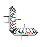
The Bevel Gear Constraint block represents a kinematic constraint between two gear bodies with intersecting rotation axes held at a specified angle. The base and follower frame ports identify the connection frames on the gear bodies. The gear rotation axes coincide with the connection frame z-axes. The gears rotate at a fixed velocity ratio determined by the gear pitch radii.
The block represents only the kinematic constraint characteristic to a bevel gear system. Gear inertia and geometry are solid properties that you must specify using solid blocks. The gear constraint model is ideal. Backlash and gear losses due to Coulomb and viscous friction between teeth are ignored. You can, however, model viscous friction at joints by specifying damping coefficients in the joint blocks.
Gear Geometry
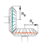
The bevel gear constraint is parameterized in terms of the dimensions of the gear
pitch circles. The pitch circles are imaginary circles concentric with the gear
bodies and tangent to the tooth contact point. The pitch radii, labeled
RB and
RF in the figure, are the outer
radii that the gears would have if they were reduced to friction cones in mutual
contact.
Gear Assembly
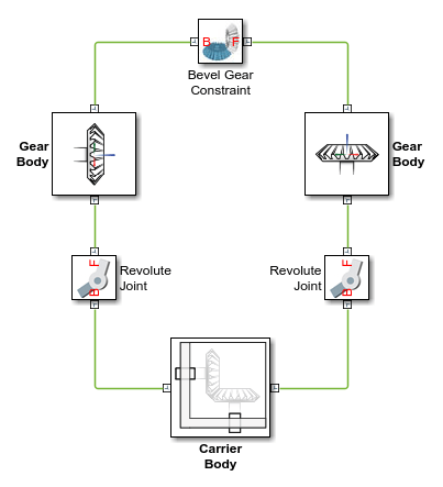
Gear constraints occur in closed kinematic loops. The figure shows the closed-loop topology of a simple bevel gear model. Joint blocks connect the gear bodies to a common fixture or carrier, defining the maximum degrees of freedom between them. A Bevel Gear Constraint block connects the gear bodies, eliminating one degree of freedom and effectively coupling the gear motions.
Assembly Requirements
The block imposes special restrictions on the relative positions and orientations of the gear connection frames. The restrictions ensure that the gears assemble only at distances and angles suitable for meshing. The block enforces the restrictions during model assembly, when it first attempts to place the gears in mesh, but relies on the remainder of the model to keep the gears in mesh during simulation.
Position Restrictions
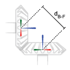
The distance between the base and follower frame origins must be such that, at the given shaft angle and pitch radii, the gear pitch circles are tangent to each other. This distance, denoted dB-F, follows from the law of cosines:
where RB is the pitch radius of the base gear, RF is the pitch radius of the follower gear, and θShaft is the intersection angle between the rotation axes.
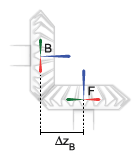
The distance between the base and follower frame origins along the z-axis of the base frame, denoted ΔzB, must be equal to:
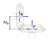
The distance between the base and follower frame origins along the z-axis of the follower frame, denoted ΔzF, must be equal to:
Orientation Restrictions
The imaginary lines extending from the base and follower z-axes must intersect at the shaft angle set in the block dialog box. The angle is denoted θB-F in the figure. If the Shaft Axes parameter is set to
Perpendicular, the angle is 90°.
Examples

Ports
Frame
Parameters
Extended Capabilities
Version History
Introduced in R2013b
You can also select a web site from the following list:
Americas
- América Latina (Español)
- Canada (English)
- United States (English)
Europe
- Belgium (English)
- Denmark (English)
- Deutschland (Deutsch)
- España (Español)
- Finland (English)
- France (Français)
- Ireland (English)
- Italia (Italiano)
- Luxembourg (English)
- Netherlands (English)
- Norway (English)
- Österreich (Deutsch)
- Portugal (English)
- Sweden (English)
- Switzerland
- United Kingdom (English)